
Subsurface energy decisions (where to drill a geothermal doublet, how much CO₂ a formation can hold, how hard to inject near a fault) rest on coupled physics that is expensive to simulate and hard to trust. We develop simulation methods that are fast enough for design studies and accurate enough to support engineering decisions.
Current work
A multiphysics finite-element simulator for porous and fractured rock, built on MFEM and hypre from Lawrence Livermore National Laboratory. It couples:
- Flow: single-phase, two-phase, black-oil, CO₂–brine with dissolution, and compositional with an equation-of-state flash.
- Heat: advection and conduction in the rock and the fluid.
- Mechanics: linear elastic, Drucker–Prager plastic and large-deformation rock, with Biot poroelasticity solved by fixed-stress splitting.
- Chemistry: mineral dissolution and precipitation, with porosity and permeability that evolve as the rock changes.
- Discontinuities: embedded discrete fractures, cohesive hydraulic fractures, phase-field fracture and frictional faults.
Beside the rock, a network solver models the wells and the surface lines that join them: tubing, chokes, manifolds and rate controls that hand over to a pressure limit, with gas and liquid flowing together by drift flux (Shi et al., 2005). It runs in parallel over MPI, and the build supports GPU acceleration for selected operators. It is in production as TerraNavitas Subsurface, with a browser workbench that teams use to build, run and inspect cases.
Verification
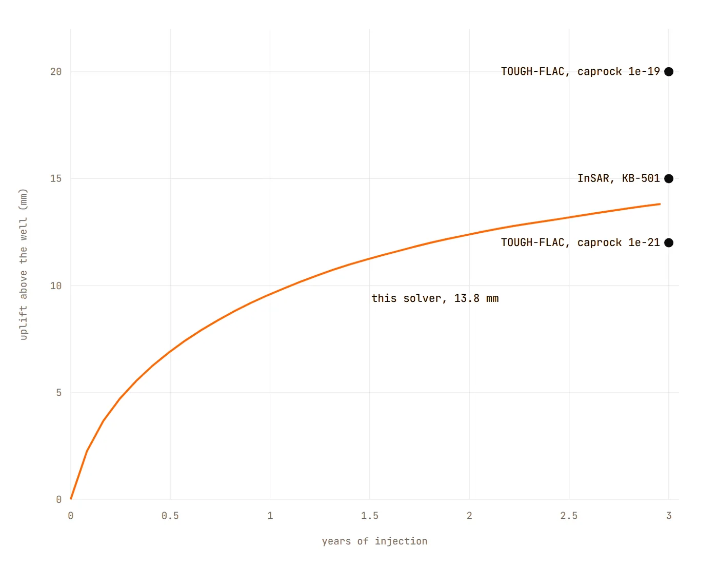
The core physics is checked against classic analytic solutions in automated tests: Terzaghi and Mandel consolidation, the Kirsch plate, Buckley–Leverett and McWhorter–Sunada displacement, and KGD and penny-shaped hydraulic fractures. Beyond closed forms, it is held to a community benchmark and to field data. For the Class et al. (2009) problem of CO₂ leaking up an abandoned well, its arrival time, peak, time of peak and 1000-day leakage all fall inside the range the ten participating codes reported. Over the In Salah injector KB-501 it lifts the ground 13.8 mm in three years, between the 12 mm of the published coupled model and the about 15 mm measured by satellite radar.
The well-network solver is held to closed forms too: mass and enthalpy balance and the orifice law across a production manifold, and the moment a well leaves its rate target as its reservoir depletes. Its two-phase flow reduces exactly to the single-phase solver when no gas flows, and comes within a few percent of the gas saturation and drift velocities Pan et al. (2011) report for an air–water well. Comparing SPE1 and SPE5 with their published results, and extending verification to heat and chemistry, is ongoing work.
Before running a case, the solver checks it, states which physics it will solve, and rejects combinations it does not yet support, with a message the engineer can act on.
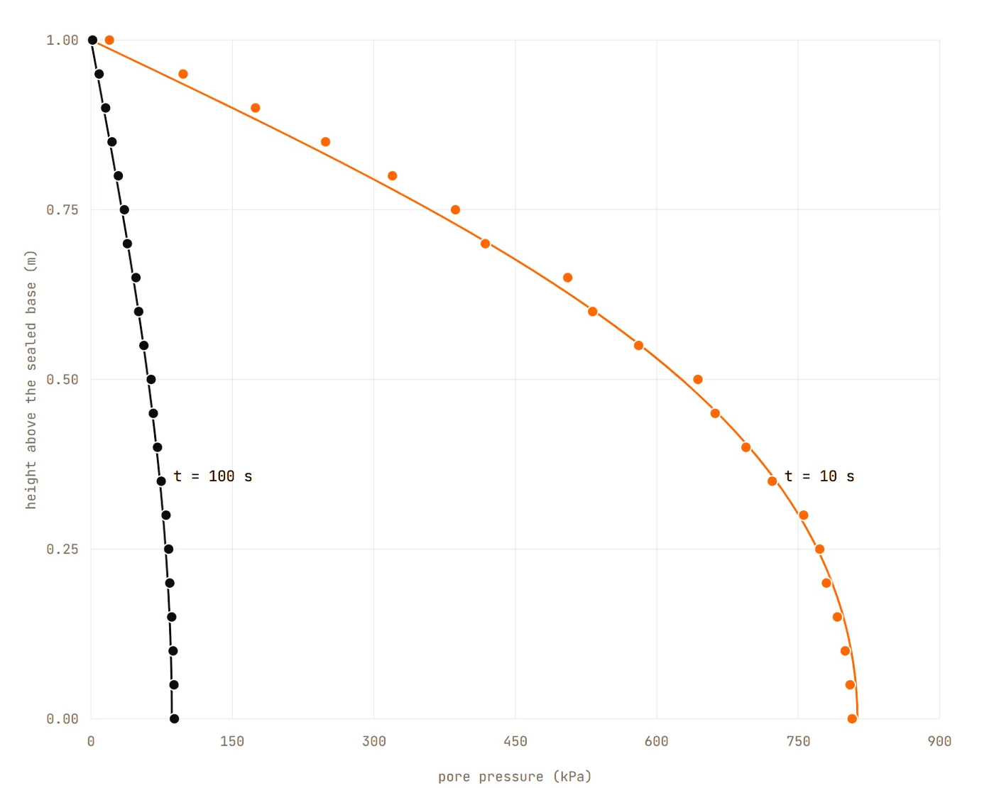
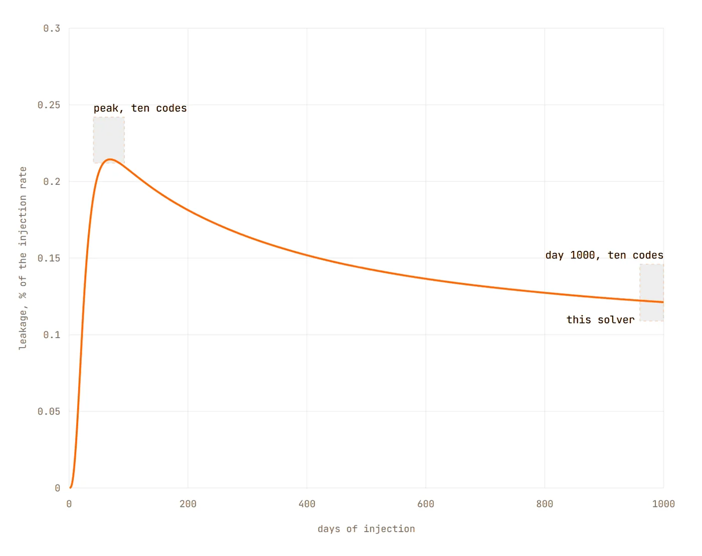
- references the simulator is held to: seven analytic solutions and a ten-code benchmark
- 8references the simulator is held to: seven analytic solutions and a ten-code benchmark
- In Salah ground uplift in three years, against about 15 mm measured from orbit
- 13.8 mmIn Salah ground uplift in three years, against about 15 mm measured from orbitPublished coupled model: 12 mm.
- to simulate 30 years of a geothermal doublet on 4 cores
- 91 sto simulate 30 years of a geothermal doublet on 4 cores
Applications
- Geothermal energy: the thermal front between injector and producer over a project's life.
- Carbon storage: plume migration, dissolution trapping, pressure build-up and caprock stress.
- Induced seismicity: injection near a fault, the Coulomb ratio and the onset of slip.
- Hydraulic stimulation: fracture growth checked against analytic solutions.
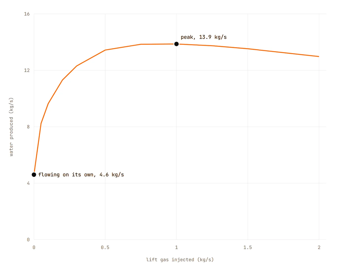
- Production engineering: gas lift, wellhead chokes and the surface network between the wells and the plant.
Physical-systems modeling
For engineered systems, our physical-systems modeling library composes components (electrical, mechanical, thermal, magnetic and fluid) connected by typed ports, and compiles them into differential-algebraic equations with exact derivatives. Each component cites the source of its equations so that it can be checked, and 79 components are compared against an established commercial reference tool. The library is in development.
Open problems
- Surrogate models with physical guarantees. Reduced-order models (proper orthogonal decomposition, discrete empirical interpolation, operator inference) trained on full-physics runs, and trusted only within the ranges where they have been checked.
- Uncertainty quantification at field scale. Sensitivity screening, sampling and Bayesian calibration run as one workflow, so a forecast carries its P10, P50 and P90.
- Fully coupled thermo-hydro-mechanical-chemical problems. Heat with mechanics, and chemistry with multiphase flow, at time steps a field study can afford.
- GPU acceleration. Moving the heaviest operators to GPUs without changing the physics a user sees.
- Coupled well and reservoir simulation. Well hydraulics limit what a reservoir can deliver, and the reservoir sets the conditions in the well. We plan to couple them, first through lift curves from the network solver and then as one system where wells share a surface network.
- Agent-built meshes. Mesh generation is the bottleneck of high-fidelity simulation. Using a mesher driven by its own description language, an agent converts an engineer's description into a model, checks each version with the mesher, and reports what it could not build. Open questions include reliable mesh-size estimates before meshing, and thin, wide regions where tetrahedral elements degrade.
The simulator is available as TerraNavitas Subsurface. terranavitas.ai/subsurface ↗ (opens in a new tab)